Axis control
This section describes the control algorithm for azimuth and elevation axes.
The control algorithm performs the main actions listed bellow. They are done in the written order. Some management actions are not listed for simplicity.
Read Drives System Data
Get User Command
Get Position Feedback
Execute Control Algorithm
Calculate Electrical Angle
Write Drives Data
Write Axis State
Publish Data
Update Settings
Read drives system data
Get user command
Get position feedback
This function waits up to 100us to get a new value from the EIB. If the data arrives on time it calculates the mean value for relative positions, speed from EIB, and absolute positions.
For relative positions, only the heads without error are used for the calculation. If one head fails while the system is working, the mean will not use the failed head to calculate the mean automatically. This position is the one used by control algorithm to control the axis (see Position control algorithm section).
For absolute position, only the heads with a reference valid flag are used to calculate the absolute mean value. This value is not used in the control algorithm for anything.
If data is not received on time, the data will be extrapolated with the last valid data. This extrapolation is done for each head data and for the axis data (valid heads data mean).
Execute control algorithm
In this function the control algorithms are executed. For both axis the position control algorithm is executed. For Azimuth, the damping control algorithm is also executed.
Position control algorithm
The position control algorithm calculates the torque needed to make the actual position match the setpoint position.
The position control used is a standard used for precise positioning control.
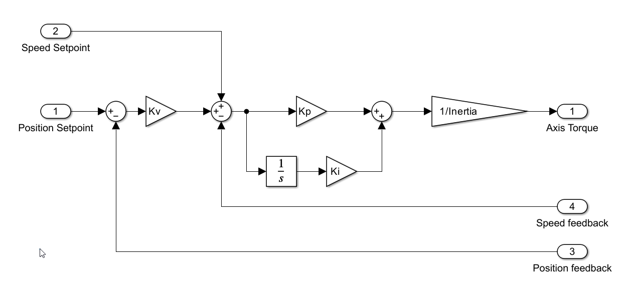
As can be seen in the diagram above, the actual position is compared with the actual setpoint, and using a gain the speed setpoint is calculated. This speed setpoint is compared with the actual speed to apply a PI (proportional and integral) to obtain the acceleration setpoint. This acceleration setpoint is converted to a torque setpoint. Lastly the total torque is divided into the active drives, that would be sent to the motors in the write drives data step.
The control includes a speed feedforward. The speed feedforward applies the speed setpoint calculated by the trajectory generator directly to the speed setpoint in the control algorithm. The speed feedforward eliminates the position error when the axis is moving, but it generates an overshoot when the axis is stopped or when there is a speed change. The feedforward is necessary during tracking, to eliminate the tracking following error but the overshoot could increase the stabilization time after an slew. To avoid this, the feedforward is deactivated as soon as an slew is detected by the trajectory generator. The feedforward is then activated once the slew is finished in a gradual way, to avoid any undesired perturbation.
In the control loop algorithm, the position variable is always the same to avoid any steps after doing the reference. An step in the position means a step in torque. As the only variable that is valid from the start of the EIB is the relative position, the used position for control the axis is the relative position. The absolute position will be an offset for the trajectory generator that would applied to the generated trajectory to command the axis with the equivalent relative position reference. This offset value is updated with the command writeReference (see Axis Manager for more info).
Publish Data
This method will prepare the data to send to the TMA-PXI. The data sent is:
Axis State. The state of the axis Manager. It is an U32 number where the first byte indicates de plcOpenState and the second byte is the overallState. The other two bytes are free.
Excitation Data. It is the excitation value used for axis identification
Axis Absolute Position. It is the axis absolute position read from active heads.
Axis Position. It is the relative position used by the axis controller + the reference data. It should be very similar to the absolute position all around the telescope range, but ti must be same in the position where the homing was done.
Axis Speed. It is the speed of the axis calculated byt derivation of the position. This speed is used by the controller for closing the speed loop.
Hall 1 Electrical Angle. Electrical angle measured by the hall sensor 1. This is the only sensor for azimuth axis.
Hall 2 Electrical Angle. Electrical angle measured by the hall sensor 2. No data in azimuth axis.
Encoder Electrical Angle 1. Electrical angle calculated with encoder heads data (axis position), this data is equivalent to the Hall 1 Electrical Angle.
Encoder Electrical Angle 2. Electrical angle calculated with encoder heads data (axis position), this data is equivalent to the Hall 2 Electrical Angle.
Control Torque 1. Force demanded by the active damping control algorithm for the X direction. In elevation axis this value is 0.
Control Torque 2. Force demanded by the active damping control algorithm for the Y direction. In elevation axis this value is 0.
Control Torque 3. Torque demanded in drive 15 produced by active damping control algorithms in X and Y directions. In elevation axis this value is 0.
Control Torque 4. Torque demanded in drive 0 produced by active damping control algorithms in X and Y directions. In elevation axis this value is 0.
Control Torque 5. Torque demanded by the position control algorithm.
Control Torque 6. Torque demanded by the position control algorithm before any filtering
Control Torque 7. Torque demanded by the position control algorithm before low-pass filtering but after max torque variation filter.
Control Torque 8. Free.
Active drives. Number of active drives in the axis.
Axis Torque. Torque demanded by the position control algorithm.
Head 1. Encoder Head 1 position info. All the offset are included to allow a better comparison with the absolute value.
Head 2. Encoder Head 2 position info. All the offset are included to allow a better comparison with the absolute value.
Head 3. Encoder Head 3 position info. All the offset are included to allow a better comparison with the absolute value.
Head 4. Encoder Head 4 position info. All the offset are included to allow a better comparison with the absolute value.
Position Setpoint. Position setpoint calculated by the trajectory generator and used by the control algorithm in the position loop.
Speed Setpoint. Speed setpoint calculated by the trajectory generator and used by the control algorithm in the speed loop.
us counter. The latest value of the us counter. Allows debugging control loop timing
ControllerTime us. us used by the control algorithm task to fulfill all the tasks in one iteration
FinishedLateCounter. It is counter that counts the number of times that the control algorithm code uses too much time to execute. The counter resets to zero when the axis is reset.
Timestamp. Timestamp of the AXES-PXI when all publishing data is packed to sent.
ObserverABSCorrection. Correction value made by the position observer. Allow debugging the observer status.
Debug1. Free value that could be used for testing or debugging.
In version 6.1.0 used to display late trajectory generation value
FollowingDistanceRMS. Following error RMS value (see following error RMS calculation for more info)
Encoder Data Received Time. The time when the data from the encoder is gotten in the AXES-PXI.
Encoder Data Required Time. The time when the data from the encoder is needed in the axis control algorithm.
Encoder Frame Counter. A counter sent by the EIB to know if any data sent from the EIB is lost. No data is lost if the counter has all the numbers from 0 to 255.
Axis Acceleration. Actual axis acceleration (see Acceleration and jerk calculation)
Axis Jerk. Actual axis jerk (see Acceleration and jerk calculation)
Acceleration and Jerk calculation
The acceleration is calculated by simple derivation of the actual speed (that is obtained by derivation of the actual position), then a lowpass filter is used to get a readable acceleration value. The lowpass filter can be managed by the #TODO: put filter settings.
The jerk is calculated by simple derivation of the filtered acceleration.
The filter is restarted every axis reset.